Of Old Radios And Related Items--Published Monthly
Motorola 53LC3
The Missing Link PortableBy JEROME WIELAND
WEB EDITION
Sometimes a seemingly insignificant, but large set is worth a second look. And to find that it contains subminiature tubes poses a mystery too intriguing to pass up. (Editor)
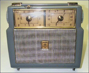
I usually don't give portables a second glance, particularly if they are plastic. However, this one, shown in Figure 1, caught my eye because it seemed to have two dials. When I looked closer, one dial was a clock. Rather unusual I thought. It was also a Motorola which raised my interest more since that's my employer. Besides being rather beat up and dirty, it was also rather large, heavy, and somewhat ugly.
I opened the back to see if it had batteries that might account for the weight. It did have a 671/2-volt pack that had leaked and corroded, a battery retaining clip, and a battery connector. The chassis was missing all its mounting screws (not a good sign). I then noticed the speaker was missing the magnet and voice coil. Broken off, I speculated.

Figure 1. The "Missing Link Portable," a Motorola Model 53LC3. The set is unusual because of its tube complement and mechanical clock.
Tube Mystery
I saw only one tube in the chassis. Did someone take the others? Hold on. I don't see any more tube sockets. What are these glass vials? I wiggled one gently and out it came. It looked like a thin, flat vacuum tube with wires in a row for pins. It had a Motorola logo and ID number. There were two other such tubes, one completely covered with what appeared to be a conductive coating, probably for shielding. I was in a hurry, so I left without making an offer on what I considered an undesirable radio.
At home I consulted my RCA tube manuals and could find no mention of any such tubes. My tube tester did not have a socket that would accept such a pin configuration. I began to wonder why the Motorola designers would use such a compact tube in such a large portable. The more I thought about the tubes, the more they reminded me of early transistors with in-line wire pins. I thought of Darwin and evolution. Visions of these glass vial tubes morphing into transistors danced in my head. Had I found a missing link?
The next week I returned to the antique shop and bought the radio for ten dollars expecting some of the unusual tubes to be dead and probably difficult or impossible to replace. At home, the first order of business was cleaning. The battery terminals were so corroded that the connector could not be removed. The terminal separated from the battery pack. The D-cell spring terminals were also very corroded.

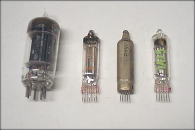
Figure 2. The radio's tubes, from left to right: a miniature 3S4 and three subminiatures a 1V6, a 1AH4 and a 1AJ5.
The radio model number 53LC3 indicates a 1953 production year. The tube location diagram listed the following tube types: 1AJ5, 1V6, 1AH4, 3S4. Only the 3S4 audio output tube is a conventional size tube. The "vials" have 5 to 7 terminals. The tubes are shown in Figure 2. All the in-line sockets are subminiature tubes with 1.5-volt filaments. The 1AJ5 is a 6-lead sharp cutoff pentode and diode. The 1V6 is a 7-lead triode-pentode converter and the 1AH4 is a 5-lead RF pentode.
The tubes and sockets are marked with a paint dot to indicate to which side of the socket the tube should be offset. It would be easy to insert the tubes incorrectly if one ignores these dots. This caution is noted on the tube location diagram on the back cover.
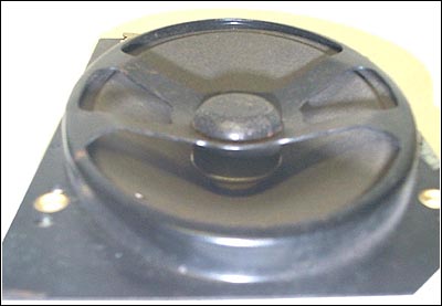
The chassis was easily removed since all the mounting screws were missing. The clock had no electrical connection and was a mechanical model that started working when wound. I then removed the speaker, still thinking it was damaged. When it was loose, I noticed a metal basket in front of the cone. As Figure 3 shows, the magnet was mounted to this basket and the voice coil was on the front of the cone! I have never seen this speaker design before. This configuration saves about an inch in speaker depth. Since the 671/2-volt battery is mounted behind the speaker, I suppose this inch savings helped reduce the thickness of the radio, but it is still about three inches thick.

Figure 3. The radio's compact speaker is designed with the permanent magnet and voice coil mounted in front of the speaker cone.

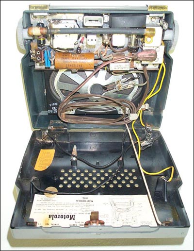
Figure 4. An interior view of the radio with what first appeared to be a damaged speaker.
Before applying power, I tested the conventional 3S4 tube and found it to be good. An ohmmeter check of the vial tubes showed continuity between an outside terminal and a middle one on each tube. This, I assumed, was the filament. The chassis components and wiring appeared to be in good condition, so I slowly applied power through a Variac. The radio sprang to life and performed well. Alignment was very close to optimal. The internal ferrite loopstick antenna provides good AM reception. A thorough case cleaning with soapy water brought the radio to respectable condition. Figure 4 shows the radio with the housing open.
It is a mystery to me why the Motorola designers used subminiature tubes and a special speaker in a portable that is not light or small. It would be interesting to know how many other manufacturers used these small tubes, and if they took better advantage of their size than Motorola did. Since transistors began appearing in portables in only a few more years, the product life of these small tubes must have been limited.
(Jerry Wieland, 780 Charleston Ln. Hoffman Estates, IL 60195. E-mail: jeromewieland@comcast.net)
Jerry Wieland is an electrical engineer working in cellular phone development at Motorola. His interest in old radios began at age 12 when he started listening to shortwave broadcasts on a 1930s Silvertone console.
�
| [Free Sample] [Books, etc., For Sale] [Subscribe to A.R.C./Renew] [Classified Ads] [Auction Prices] [Event Calendar] [Links] [Home] [Issue Archives] [Book Reviews] [Subscription Information] [A.R.C. FAQ] URL = http://www.antiqueradio.com/Feb04_Wieland_MissingLink.html Copyright © 1996-2004 by John V. Terrey - For personal use only. Last revised: January 30, 2004. For Customer Assistance please contact ARC@antiqueradio.com or call (866) 371-0512 Pages designed/maintained by Wayward Fluffy Publications
Antique Radio Classified |