VOLUME 15 JUNE 1998 NUMBER 6
VOLUME 15 JUNE 1998 NUMBER 6
The "Queen" of Induction Coils
Web EditionBY Dave Gonshor
In this article Dave Gonshor describes a rare Queen & Co. induction coil and underscores the significance of the induction or spark coil to early wireless. (Editor)
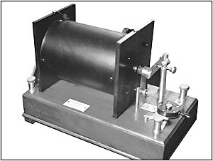
Guglielmo Marconi received the first transatlantic wireless message at Cabot Tower in Newfoundland on December 12, 1901. The message was sent in Morse code, not voice. In part, this remarkable event was made possible because of a basic understanding of the physics of coils. The Queen & Co. induction coil shown in Figure 1 is an apparatus that forms the heart of a wireless spark transmitter.
Figure 1. The Queen & Co. induction coil. The label reads "Queen & Co., Makers, Philadelphia."
The Queen & Co. induction coil is similar in construction to other induction coils of the time (circa 1915), most notably the widely used Ruhm-korff coil. The Queen coil has the added feature of an on-off switch.Induction coils were used in wireless spark transmitters to step-up a pulsed voltage to a potential sufficient to break down a spark gap. The breakdown of a spark gap produces radio frequency energy which excites a resonant circuit, thus producing tuned frequency radiation related to the pulsed voltage. This was the primary means of radio transmission prior to the use of the vacuum tube. A telegraph key produced the information to be transmitted via closure of contacts consistent with the Morse code. The secret of how opening and closing of key contacts produces a signal that can be stepped up to a voltage that would spark a gap lies in the design of the induction coil.
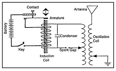
A schematic diagram for a basic spark transmitter is shown in Figure 2. A series connection of a battery, a key, a set of contacts and the induction coil primary form the low voltage circuit of the transmitter. Closing the key contacts applies the battery voltage through the contacts to the primary of the coil. Once the coil is energized, it acts as an electromagnet to attract an armature. When the electromagnet pulls the armature towards it, the primary contacts are opened thus de-energizing the coil. The spring action of the contact assembly recloses the contacts, and the primary coil is again energized. This process is repeated many times a second to produce an interrupted, or pulsating, DC voltage across the primary coil. The induction coil steps up these low-voltage pulses to produce high-voltage pulses in its secondary winding.
Figure 2. A schematic diagram of a basic spark transmitter.
The high voltage secondary of the induction coil is connected to a condenser, which is a Leyden jar or a heavy glass plate condenser, which feeds the spark gap and the primary of the oscillation coil. The condenser and the oscillation coil primary form the tuned tank circuit, which establishes the transmitter frequency. The oscillation coil secondary is connected to the transmitting antenna and to ground, and is also tuned to the same resonant frequency as determined by the oscillation coil secondary inductance and the capacitance of the antenna. The transmitted power is determined by the length of the arc which could be developed across the gap; the longer the spark the more power transmitted.(Dave Gonshor, 7121 Jellison St., Littleton, CO 80123)
Dave Gonshor is a registered professional electrical engineer whose interest in old radios spans wireless to depression era sets.