Of Old Radios And Related Items--Published Monthly
General Electric Model RC-1671A
Radio/Phonograph RestorationBY DANIEL SCHOO
Web Edition
Sometimes restoring a set becomes a long-range project. However, the pleasure of combining the project with presenting it as a gift makes it all worthwhile, as illustrated in the following article. (Editor)
In 1995, a friend and I were going through an old vacated office and tech shop where I work. The former occupants had moved to a new location and left a bunch of things behind. One of the things was a General Electric Model RC-1671A stereo AM/FM radio/record player made in 1964. The tabletop unit was not in too bad shape and just reeked of that wonderful 1960s styling that I grew up with. It had a veneered, dark walnut finish, wood cabinet, and the speaker grille cloth was that cane type material popular back then. Besides all that, it had tubes!
Years ago, I remember my uncle had one of these sets, and to my 13-year-old eyes, it was just about the most beautiful thing I had ever seen. I asked the supervisor if we could have it, and he agreed. I let my friend take it home, as I did not have room for it. He put it in his garage, and it sat there for 14 years.
My restoration of this set started as the result of my father's wish to have a record player to play his old records. Although you can still buy a record player today, the selection is not very plentiful, the mechanisms are cheaply made, and many contemporary players are not designed to play both the old 78 rpm disks and 33 rpm albums.
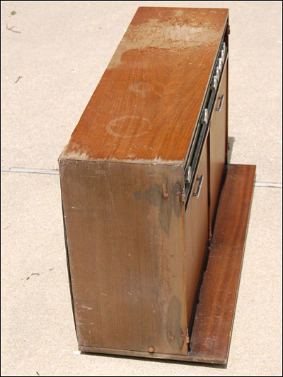
Figure 2. End view showing water damage.For months, I looked around at Hamfests, radio swap meets and garage sales for something appropriate. I found a few record players, but they were either junk or priced too high or both. I wanted something classy that would sound nice but not have to be as big as a floor console.
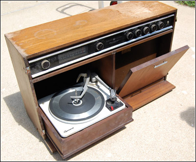
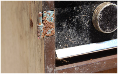
After an unsuccessful search for a record player for my dad, I remembered the old GE, and I asked my friend if I could have it. He was only too glad to get it out of his garage. Figure 1 (see print version or complete PDF) shows the set after retrieval. While it was in storage, water had dripped on it staining the wood and rusting two of the hinges that the left speaker hangs on. Figures 2 and 3 show the water-damaged cabinet. Figure 4 shows hinge and knob damage. And so, the project began in early August of 2009.
The GE Model RC-1671A
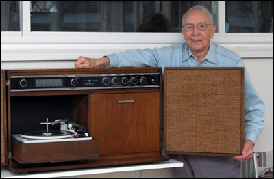
This system could be called a mini-console at 32 inches wide and 20 inches tall. The two speakers are on hinges and swing out from the front, allowing the user to fold them closed when not in use. The hinges are used to electrically connect the speakers to the stereo. You can also lift the speakers off the hinges and connect them remotely with standard RCA-type audio cables.
Figure 3. This open view of the cabinet shows the water damage to the top veneer. The compartment to the right is for record storage.There is a fold-down record changer on the left side and a tilt-open storage compartment on the right for records. The console can be set on a shelf or table, or you could mount it on the wall using an included template to locate the mounting screws in the proper locations. Figure 5 (see print version or complete PDF) shows a rear view of the system.
Music Distribution System (MDS)
One of the unique features of this product is that it has an option called a Music Distribution System (MDS), or more commonly known in advertising as "GE Porta-Fi." The MDS is a form of wireless remote speaker system. There is a separate speaker that you could take to any room in your home, plug it into an AC outlet, and it would play whatever audio was on the main stereo. Figure 6 (see print version or complete PDF) shows two versions of the remote speaker.
The way it works is that an optional MDS adapter was installed in a special location inside the main stereo cabinet. The stereo was prewired for it, and the MDS adapter simply plugged into the existing wiring. The MDS adapter consisted of a low power FM monaural radio transmitter operating at a frequency of 250 kHz. The radio frequency output signal was coupled through a high pass filter into the AC power line. The AC power line wiring carried the signal throughout the house. The space reserved for the MDS unit can be seen on the lower left of Figure 5 (see print version or complete PDF).
The remote speaker has an FM receiver in it that receives the 250 kHz signal from the power line through a high pass filter. This is known as a "carrier current" system and is still used for things like wireless intercoms, baby monitors and low power, local program broadcasting. An alternate B frequency of 300 kHz could be used to prevent interference from a similar neighboring system.
Figure 4. An example of damage to the wood, hinges, panel, and knobs can be seen here.This set did not have the MDS option installed when we found it. A couple of years later, I found a GE MDS transmitter and remote speaker at a garage sale. I knew exactly what it was, so I bought it. I gave it to my friend and he put it in his garage along with the stereo. A short time later, I found another bigger and better GE MDS remote speaker on the pile in the donation auction at the Antique Radio Club of Illinois Radiofest, so I picked that up and gave it to him. I have not seen another one since. Rear views of both versions of the remote speakers are seen in Figure 7 (see print version or complete PDF).
Electrical Restoration
For the electrical restoration work, I replaced a couple of selenium rectifiers in the radio and in the MDS component chassis. I don't bother testing selenium rectifiers. I assume that they are all bad or will be, and that way, I never get surprised by an unexpected failure.
The circuit design is such that I could replace the selenium rectifiers with silicon rectifier diodes and not have to make any modifications. I rebuilt a big multisection cardboard electrolytic on the audio chassis and replaced several small electrolytics in the MDS chassis. Figure 8 (see print version or complete PDF) shows both before and after views of the amplifier chassis, including the rebuilt paper electrolytic capacitor. There are several upright aluminum can electrolytics in the radio and the MDS chassis, and they tested good.
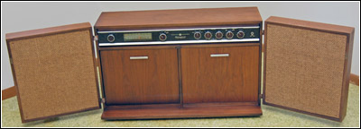
Figure 10. The restored General Electric Model RC-1671A stereo, AM/FM radio/record player, shown complete with swing-out speakers.To check these old can-type electrolytics I measure the Equivalent Series Resistance (ESR) with a digital ESR tester. The ESR is a measurement of the internal resistance of a capacitor. It's like having a resistor in series with the capacitor inside the can. If the electrolyte dries out, its resistance goes up and that becomes an impediment to the function of the capacitor. The ESR should be in the low ohms to sub-ohm range depending on the capacity and voltage rating.
I have seen electrolytic capacitors measure perfectly good for capacity but not work because of high ESR. If the ESR is not too high, I do a leakage test. I apply a DC voltage to the capacitor slowly ramping it up while watching the leakage current. If I can get to full rated voltage or better with low leakage, that's good enough. Again, leakage current depends on the capacity and voltage rating of the capacitor.
The radio was in pretty good shape. Besides the selenium rectifier, I replaced a couple of tubes.
The audio output uses a pair of Type 7189 pentodes in single-ended Class A configuration, one tube for each channel. The audio chassis uses a Type 5Y3 rectifier and a single Type 12AX7 twin triode as a preamp/driver for both channels. The 7189 sockets were baked, and the solder joints didn't look good.
Any old, printed, circuit-based equipment like this should have all of the tube sockets resoldered. Repeated heating and cooling from rectifiers, power resistors, and power tubes crack the solder around the pins in the PC board, and they go intermittent or open. Even a close inspection with a magnifying glass will not show any problems, but they are there. I resoldered every joint on the printed circuit board in the audio amplifier chassis and several in the radio.
The rear view of the fully restored system, including the added MDS unit, is shown in Figure 9 (see print version or complete PDF).
The Record Changer Restoration
The record changer is a lower end model made by Garrard but sturdily built. It has a GE ceramic cartridge installed. The changer was filthy but in good condition. Even the idler wheel was still lively and pliable. All that it needed was a good cleaning and re-lubrication.
The changer was actually working when I got it, but there was one minor problem: It would not shut off after the last record was played. I scouted around the mechanism, and I determined that there must be a spring missing that pulled on a lever. I was able to make the changer work by lightly pushing the lever with my finger. Sure enough, I found a loose spring, and when I connected it up where I thought it should go, the changer worked. I found a new stylus for the cartridge at West-Tech services in Ohio.
Figure 12. Daniel's father, Donald, is pleased with his "new" record player.The Cabinet Restoration
The cabinet was more of a challenge. The control panel and cabinet were filthy and needed a good cleaning. The knobs had dirt and grime imbedded in the grooves. Inside, it was pretty dusty, so I took it out on the driveway and blew it out with a leaf blower.
I sanded the sides and top of the cabinet to deal with the serious water stains. I had to be careful because the veneer is paper thin. After that, I applied oxalic acid repeatedly to the bad side to bleach out the black iron stains. That took most of a day and it cleared up almost all of the stains.
After the wood dried though, some of the stain came back. I completed the job by applying a light coat of walnut stain. That really perked things up. I removed the rusty hinges and bead-blasted them. That took off all the rust, but they were badly pitted in places. They were heavily plated with copper because they are used as the electrical connection for the speakers, and the plating prevented them from total ruin.
A Happy Ending
After the restoration work, I installed the MDS unit and it works fairly well. Figures 10 and 11 (see print version or complete PDF) show the final result. However, electrical noise from sources such as domestic solid-state light dimmers (which were not around in 1964) affect it.
My wife Donna and I took the set over to my dad on his birthday, and he was like a child with a new puppy, see Figure 12. His eyes lit up and he got all excited. He played records the rest of the time we were there, and I think he's been playing them every day since.
References:
Sams Photofacts Set 674, folder 9
Sams Photofacts Set 671, folder 11
© 2009 Daniel Schoo
Daniel Schoo, a frequent contributor to A.R.C, is an electronics design designer with a lifetime interest in antique technology, especially radio and television equipment. In addition to his collection of 1930s and 1940s radios and video cassette recorders, he has a large collection of vintage tubes, neon lamps, and tube and data books.
|
[Free Sample] [Books, etc., For Sale] [Subscribe to A.R.C./Renew] [Classified Ads] [Auction Prices] [Event Calendar] [Links] [Home] [Issue Archives] [Book Reviews] [Subscription Information] [A.R.C. FAQ]URL = http://www.antiqueradio.com/Jun10_Schoo_GERestoration.html Copyright © 1996-2010 by John V. Terrey - For personal use only. Last revised: May 27, 2010. For Customer Assistance please contact ARC@antiqueradio.com or call (866) 371-0512 toll free Antique Radio Classified |
