Of Old Radios And Related Items--Published Monthly
SECO Crystal Set
BY PHILIP BLISS
Web Edition
Phil Bliss augments the coverage of SECO in "Crystal Clear," the extensive two-volume reference by Maurice l. Sievers for American crystal sets. (Editor)
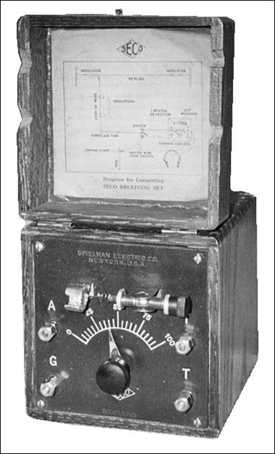
The crystal set shown in Figure 1 is a recent purchase. It was manufactured in the 1923-1924 time frame and was probably the only design by Spielman Electric Company marketed under the SECO name.
I wanted to share this information with A.R.C because some of your readers might be interested in photos and details that are not included on pages 193 and 194 in the resource guide Crystal Clear, Volume 1.
The box shown in Figure 2 (see print version) measures 43/8" long x 43/8" wide x 55/8" high. Shown in Figure 3 is the Bakelite panel with the crystal and catwhisker mounted parallel to the panel. The diagram for connecting the crystal set to the antenna, ground and telephones (referred to today as headphones) is shown in Figure 4.
The antenna and tuning coils, shown in Figures 5 and 6 (see print version), are wound on cardboard forms with a smaller antenna coil inside the tuning coil. The slide on the tuning coil is operated by a knob on the face of the panel. This circuit arrangement allows for very good selectivity.
Reference:
Sievers, Maurice L. Crystal Clear, Volume 1. Chandler, Arizona: Sonoran Publishing, LLC., 1995.
(Philip Bliss, 183 Austin Ryan Dr., Kingsland, GA 31548-6190)
Philip Bliss, a retired educator, can trace his involvement with electrical projects to making his first crystal set at age eight. Subsequently, he made many toys with his prized possessions -- batteries, bulbs and wires -- and never had to say, "I'm bored." His Army career from 1952 to 1954 as a radio repairman has been followed by a lifetime of radio collecting.
Figure 1. The SECO crystal set.
Figure 3. A close view of the crystal set panel showing the crystal, the tuning knob and the binding posts for antenna, ground, and telephone (or phones).
Figure 4. The diagram for connecting the set. Note that a switch was available to connect the antenna to ground when the crystal set was not being used.
Figure 5. A side view of the tuning coil showing one winding inside the larger winding.
| [Free Sample] [Books, etc., For Sale] [Subscribe to A.R.C./Renew] [Classified Ads] [Auction Prices] [Event Calendar] [Links] [Home] [Issue Archives] [Book Reviews] [Subscription Information] [A.R.C. FAQ] URL = http://www.antiqueradio.com/Oct06_Bliss_Seco.html Copyright © 1996-2006 by John V. Terrey - For personal use only. Last revised: September 30, 2006. For Customer Assistance please contact ARC@antiqueradio.com or call (866) 371-0512 toll free Pages designed/maintained by Wayward Fluffy Publications
Antique Radio Classified |


