VOLUME 16 AUGUST 1999 NUMBER 8
VOLUME 16 AUGUST 1999 NUMBER 8
Restoring an RCA 5Q8
WEB EDITION
You never know when a long ignored junker will suddenly take on new interest. As Walter Heskes tells us below, what hecalled a "hulk" when he first acquired it became "a great old gal" when hauled out from under his bench a few years later and given a second look. Reminds us that "second looks" are always a good idea. (Editor)
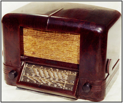
BY WALTER HESKESWith a show coming up here in the fall, my wife Lisa and I hauled out some of the junkers -- the "footrests" -- from under our bench. One was a 1940 RCA 5Q8, shown in Figure 1, a brown Bakelite hulk, which we had tested once about two years ago. After listening to it for a few moments, we determined that it needed recapping and rewiring, as well as a good cleaning and polishing. We had no interest or enthusiasm for these tasks, so we simply stuffed it into a corner on the floor and promptly forgot about it.
Figure 1. The 1940 RCA Model 5Q8 multiband radio.
Friday night, when our twin 2-year old boys finally were asleep, we ventured down to the shop to examine the 5Q8 once more and decide its fate. Indeed, we had never fallen in love with this rig, which suggested the styling of a horseshoe crab shell. We decided that our initial sentiments really hadn't changed, and we were ready to throw it out, just to reclaim some valuable elbow room under the bench.Then, we made the classic mistake of taking another really close look at this great old gal. It pulls in 3 bands -- LW, BC, SW. It is complete with all four original knobs and what appeared to be the original fiberboard back cover, which can be seen in Figure 2 (see print version), in very good condition. It includes a side-mounted tone control. The rectangular dial glass is a stunning example of mass-production silkscreening. It lists the names of scores of cities of the world in the vicinity of their shortwave broadcast frequencies, circa 1940. Today, many of those names exist only in history books, but as we started to wipe the dust off the glass, the radio sirens living within this set lured us into their clutches.
Recapping
We decided to do a quick recap and tuneup, just to make the beast presentable. We hauled it up onto the bench and loosened the bolts that hold the chassis to the cabinet. Upon removing the dusty chassis, shown in Figure 3 (see print version), we discovered that there were two dial strings -- one to drive the tuning cap and one to drive the indicator across the dial.
The indicator drive string was broken, and we couldn't very well offer a set this nice with a broken dial string, so we also planned to restring the dial after we had recapped the set. We removed the tubes and the ballast and set them aside. They had worked when we first tested the set, so we figured they still were okay.
We cleaned the dust off the chassis and quenched each of the thirsty pots with a refreshing splash of tuner degreaser. Next, we fished out our long-haired toothbrush and swabbed the air between the plates of the dusty tuning cap. This procedure often removes loose particles of dirt or dust that can create short circuits between plates as the rotor is swept across the stator. Then, we carefully removed the mica sliver from the RF trimmer on the tuning cap to clean it.
We also rubbed the oxidation and tarnish from the inside surfaces of the trimmer plates. Experience has taught us that the trimmers must be spotlessly clean or they will not yield the correct amount of capacitance, which is important to the tuneup procedure.
Beneath the chassis, which can be seen in Figure 4 (see print version), we found several wires insulated with red or green peanut brittle. We tried to avoid touching these wires, but, in several locations throughout the chassis, we were unable to prevent the dried-out insulation from dropping off the wires. We rerouted some of the damaged wires to prevent short circuits; however, where the flaking insulation left bare wires that crisscross other bare wires, we cut the uninsulated wire at its midpoint and slipped a length of appropriately colored shrink tubing over each bare segment.
Then, we soldered the wire at its midpoint and heated the tubing to conform to the bend of the wire. Yes, we simply could have replaced the wire, but recall that our plan was to recap quickly the chassis and make the unit presentable; we hadn't planned to rewire the set completely.
As we moved across the chassis, from the power supply to the RF section, every paper cap we checked was leaky, so we replaced them with new mylar caps. Resistors have a higher survival rate than paper caps, and, if these read within 20 percent of their rated value, we left them intact. Following the excellent pictorials in the appropriate Rider's spec sheet that we'd gotten from Mike (A.G.) Tannenbaum's collection, we finished recapping the set and called it a day -- or night.
While our twins napped Saturday morning, we restrung the dial. The paths were simple enough to determine from the sketch in the Rider's document. In practice, threading the end of the dial string into the eye of the tension spring, seen in Figure 5 (see print version), was the toughest task. After that, it was relatively simple to trace the path of each string around its respective pulleys. If we had a bit of slack in a string, we employed the trick of tying a couple of granny knots in the end of the string to absorb the excess and stretch the tension spring to give the string some "bite." With both strings installed, we were ready to tackle our original plan of tuning up the set.
Tuneup
The RCA engineers had anticipated the problem of aligning the set on the bench, without the benefit of a dial indicator to track the position of the tuning cap. They purposely added a protractor scale to the inside face of the tuning cap pulley. This can be seen in Figure 6 (see print version). The scale is calibrated in degrees of rotation from an imaginary stationary point. We fully opened the cap, plates unmeshed, and set the tip of our favorite little screwdriver to the 180 degree mark. Then, we referred to the specs for the appropriate degree mark to use for each step in the alignment procedure. The process was quite simple once you got the hang of it.
Later, on Saturday afternoon, after my wife and I returned from a mandatory stroll to the park and swingrides for little Maxie and brother Aaron, we returned to the bench to complete the business of aligning the set. We replaced the tubes and attached leads from our "bench" speaker to the output leads from the audio transformer. The Rider instructions were perfect and, using both our trusty Eico 324 signal generator and the digital readout of a Radio Shack DX-392 to calibrate the output of the 324, we were able to peak the IFs, the oscillator coils, and antenna trimmers for all three bands. Hooray!
Note that an especially useful feature of the DX-392 is its PLL-synthesized tuner, which can lock in at 455 kHz, the intermediate frequency of most modern superhet circuits. The procedure is simply to tune the DX-392 to 455 kHz and then, dial up the same frequency on the signal generator. Rock the tuner of the signal generator as you watch for a peak reading on the signal strength meter on the DX-392. When the meter is peaked, the signal generator is precisely tuned to the frequency displayed on the DX-392. You can use this simple calibration procedure for any required frequency.
The Speaker
We hadn't heard this set through its internal 4-inch speaker, but when we reconnected that little noisemaker and gave it a listen, it was terrible; it buzzed annoyingly when more than moderate volume was applied. It had to be fixed. After all, we already had invested our time and parts, so we had no choice.
We removed the speaker from the cabinet and examined it closely. The glue that secures the field coil cover to the speaker frame had dried out after 60 years, and now, the molded fabric disk was buzzing against the speaker frame as the cone moved. We applied some Elmer's glue to secure the cover, and we let it dry while we probed another annoyance -- a sagging grille cloth.
Though this grille cloth had far too much slack, it was original and in generally nice condition, so we knew it had to remain with the set. First, we carefully removed it from the pressboard frame. Then, we applied a thin film of Elmer's to the frame. Finally, we reattached the cloth, setting it into the fresh layer of glue and holding it taut for a few seconds until the glue started to set.
We left the speaker and grille cloth in a relatively safe spot on the overcrowded bench and turned our attention to reinstalling the dial pointer and dial glass assembly. This assembly is separate from the chassis and is secured to the bottom of the cabinet by two screws. The screws were missing, and the assembly was loose in the cabinet -- obviously unacceptable. To complicate the matter, we could not find a screw that matched the thread of the tapped holes in the support flanges, so we finally opted to install smaller diameter screws and tighten them with nuts from the inside of the cabinet. (Yes, it's not authentic, but it works.)
With the dial assembly nicely secured in the cabinet, we next installed the repaired grille cloth and its frame. When we installed the repaired speaker, pressing it firmly against its mounting bolts, we saw that it did not completely contact the frame; indeed, there was about 1/4-inch gap between the front face of the speaker and the frame. The gap was created by interference from the nuts that secured the mounting bolts to the speaker frame. We tried removing the nuts, but the bolts could not be held stationary unless we also removed the fragile grille cloth to grab the head of each bolt with a screwdriver while we loosened the respective nut. We decided not to remove the grille cloth.
The gap was unacceptable as the opening would compromise the baffling and reduce the richness of the sound from the speaker. To create an infinite baffle between the speaker and the cabinet, we needed a gasket. We used a pencil to mark the perimeter of the installed speaker. Then, we removed the speaker and applied a 3/8-inch bead of nonhardening window caulking putty along the inside of the pencil line, as shown in Figure 7 (see print version). When we reinserted the speaker, it squooshed the putty, forming a nice seal against the frame.
Obviously, either the original gasket had been lost, or perhaps we misinterpreted the engineer's design. If we had simply removed the grille cloth from the frame to expose the heads of the three bolts that secure the speaker to the frame, we might have fastened the speaker directly to the frame and avoided the need for the intermediate gasket. But if this were true, why were we given two sets of nuts for the three bolts? Why not one set of nuts and a lockwasher for each bolt? Such are the mysteries of life and radio repair.
Installing the Chassis
We now were ready to install the chassis. Perhaps we were a bit too excited, as we had neglected first to reattach the Number 44 bayonet base dial light to a clip on the right side of the dial. So, out came the chassis and in went the dial-light assembly, which we also had rewired to replace the frayed, cloth-covered insulation Then, in went the chassis.
Whoops! How to reattach the dial string to the pointer? A note in the Rider's spec sheet advises the technician to slip the lower string into a spring-loaded clip welded to the pointer. That seems simple, but what the writer ignored is that you can't get your fingers on the clip without removing the 25L6 from the chassis. Details!
Of course, slipping the string into the clip is only half the battle. You also must position the pointer so that it will travel the full width of the dial scale and properly track the calibrations from one end of the dial to the other. After a couple of trial-and-error adjustments, we had the pointer properly located on the string.
Then, sliding the set an inch or two off the edge of the bench, just enough to expose the bolt-heads, we worked from beneath the cabinet to tighten the bolts that secure the chassis to the cabinet. We also rechecked the dial scale to confirm that our settings hadn't slipped. They hadn't.
We were fortunate to have a back panel for this set. A single screw pinned the loop antenna to the punched pressboard. This seemed marginally adequate and two existing through-holes in this assembly begged for screws, so we scrounged through the junkbox and found the appropriate hardware.
With the loop secured to the back panel, we turned our attention to the loop antenna. We had resoldered the antenna and ground leads to the antenna coil, but we also wondered if an additional antenna lug might have been available to allow the user to attach a lead-in wire from an external aerial. An external aerial would be helpful for improving shortwave reception, and it seemed an oversight not to have included a connection to the set. We decided to add an external antenna lug to the outside of the back panel only if we found that an external antenna would be helpful even after peaking the IFs, the trimmer caps, and the oscillator coils using the onboard coil antenna.
Powering Up
Pulses pounding, we nearly powered-up the set when we noticed the 25L6 resting peacefully on the terrycloth towel we use to cover the bench. The towel helps protect the soft plastic finish of a cabinet when we up-end it or stand it on its side. We discovered that trick after marring the surface of a radio cabinet by grinding it into soldersplatters that were embedded in the benchtop.
We promptly plugged the 25L6 into its socket and applied power to the set. The dial light quickly brightened and gradually dimmed as the tube filaments warmed up. That was a good sign. Then, we switched the band selector to its middle setting -- the AM broadcast band. There was surprisingly good sensitivity and tracking across the dial. Then, we tried the shortwave band, which crowds the entire 5.4 to 18 Mc band into a single 6-inch span. Obviously, without bandspread tuning, selecting adjacent stations is a difficult task. Surprisingly, the set was satisfyingly "hot" upward from 8 Mc on this warm, sunny, late summer afternoon.
We quickly discovered that an external antenna helped significantly, despite our tweaks to the front-end trimmers and coils. We soon added a lug to the back panel and labeled it "SW" lest we forget its purpose.
Later, as we listened to an inventive and spirited program broadcast by an SW pirate radio station up around 8.6 Mc, we gently applied a thick film of Butcher's wax to the brown Bakelite finish. When it dried, we buffed the haze to a gleaming shine. Now, that it looks great and runs fine, the 5Q8 is another fine set that needs a respectable home when there is no installation space available in our house. So, for the moment, the safest place for the 5Q8 is back on the floor under the bench.
Reference:
Electronic Service Data is available from A.G. Tannenbaum, P.O. Box 386, Ambler PA 19002. Tel: (215) 540-8055; Fax: (215) 540-8327; On-line catalog at www.agtannenbaum.com
(Walter M. Heskes, 49 Marlin Avenue West, Edison, New Jersey 08820)
Walter Heskes, a mechanical engineer, has been a technical writer for 25 years. His radio interest began in the 1950s with his grandfather's huge Zenith console, and progressed to deconstructing radio chassis, such as his parents' yellow Catalin Fada bullet. Visits to Radio Row in Manhattan and steady perusal of Lafayette and Allied Radio catalogs widened his radio education. According to his wife Lisa, his current excuse for collecting and restoring radios is to pass them on to the twins.