VOLUME 16 JANUARY 1999 NUMBER 1
VOLUME 16 JANUARY 1999 NUMBER 1
Reinartz Home Brews
BY WILLIAM CORKUTT--Web editionWe are pleased to print William Corkutt's article on the very important regenerative circuit invented by John Reinartz in the early 1920s. Corkutt explains the operation of the Reinartz receiver and shows several examples of the receiver from his own collection. Although many variations of the circuit evolved over the years, the primary feature of the Reinartz receiver remained -- minimal interaction between the tuning and regeneration controls. (Editor)
"What early amateur or radio constructor has not heard of the famous Reinartz circuit?" asks Hugo Gernsbach, editor of Radio Craft magazine in the March 1938 issue. This issue celebrated radio's first 50 years, as measured from Heinrich Hertz's successful experiments in 1888 establishing the theoretical basis of wireless communications.
In the June 1921 issue of QST, the magazine of the American Radio Relay League, an article by John Reinartz entitled, "A Receiving Tuner for C.W." was published. This article showed considerable foresight, for by 1921, the amateur and commercial world was making the transition from spark telegraphy to vacuum tube technology. The vacuum tube transmitter was capable of generating narrow-band continuous waves (C.W.), rather than the inefficient wide-band signals produced by spark transmitters. In addition, C.W. would provide the basis for amplitude-modulated broadcasting.
In 1920, the regenerative receiver, invented by Armstrong way back in 1913, was the most sensitive and selective around. To receive Morse code the receiver was made to oscillate by feeding energy from the output back into the input. The oscillating detector beat against the keyed Morse signal to produce audible sound. The process usually required retuning the plate circuit or the detector tube each time the grid circuit was tuned to a new signal. Retuning the antenna was often required as well.
Reinartz, a well-known amateur, designed a receiver that would oscillate to whatever frequency the grid was tuned. Once set in oscillation, the C.W. code stations were immediately audible as the operator tuned across the spectrum using a single control. It was as simple as tuning today's receivers.
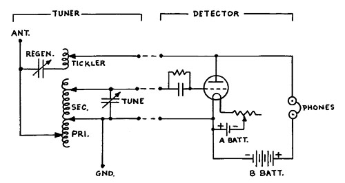
The Reinartz circuit, as shown in Figure 1, featured a combination of capacitive and inductive feedback using a specially wound spiderweb coil with tapped primary, secondary, and tickler windings. The primary winding tuned the antenna and provided loose-coupling to the secondary. Once set for a particular antenna, the primary need not be changed much.
Figure 1. The Reinartz receiver circuit.During operation, the secondary inductance was the only one entering into the actual tuning of the set. Regenerative feedback was effected by a variable capacitor in the detector plate-tickler-antenna circuit. The tickler coil provided additional feedback at the higher frequencies.
Sometime in 1921, Reinartz went commercial, and McMahon's Radio Collector Guide lists a J.L. Reinartz Co. as the manufacturer of a 1-tube regenerative receiver in that year. Page 121 of McMahon's pictorial album Vintage Radio shows a picture of a 1921 Reinartz receiver with the caption, "One of the best for C.W."
I have never seen a commercial Reinartz radio, and it is doubtful that many were manufactured. The country was about to experience the "radio boom" of late 1921 as the public discovered radio. Regenerative sets, including the Reinartz with their oscillating detectors acting as low-power transmitters, interfered with other receivers. The noninterfering TRFs, neutrodynes, and ultimately, the superheterodyne were more desirable. Yet, in my search for old radios I have, by chance, acquired several Reinartz home brews which seem to confirm the success of the Reinartz design.
Early Reinartz Home-Brew Tuner
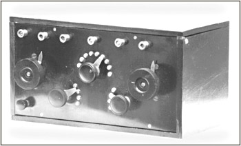
Figure 2 shows an early classic home-brew Reinartz tuner. I bought the set as a junker, and it required a good cleaning as well as the replacement of all its crumbling, rubber-coated wire.
Figure 2. The classic Reinartz tuner.The two large wood knobs control the tuning and regeneration capacitors. The central 9-position tap switch provides antenna tuning. The two 4-position tap switches vary the secondary and tickler coils. A row of metal terminals along the top of the panel connect the tuner to the antenna and external detector/amplifier. A Bakelite terminal in the lower left corner connects to ground.
The spiderweb coil appears commercially-made and is supported only by the wire leads to the tap switches -- apparently, a standard coil-mounting technique in a Reinartz. As is common in home brews, there are no end-stops for the tap switches nor any panel markings.
The 1920s 2-Tube Receiver
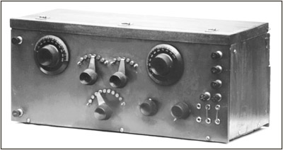
Figure 3 shows a 2-tube Reinartz receiver from the early 1920s. Again, we see the two capacitor knobs for tuning and regeneration, the 9-position tap switch for antenna tuning, the tickler tap switch (6-position), and the secondary tap switch (5-position). Two small knobs control the filaments of the WD-11 detector and amplifier tubes. Bakelite terminals are used for antenna, ground, and battery connections.
Figure 3. The 2-tube Reinartz receiver.The cluster of six tip-jacks on the lower right of the panel are for headphones; by juggling jumpers, you can arrange to operate the radio as a 1-tube or 2-tube set. The panel is made of hard rubber, which has turned a soft brown color that some collectors find attractive, even photogenic.
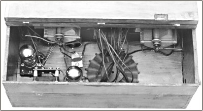
Figure 4 shows the set's interior. The spiderweb coil can be seen lying flat on the baseboard without support, except for the wires to the tap switches. The cabinet is typical home brew -- functional and rather crude.
Figure 4. The interior of a 2-tube Reinartz receiver.The 3-Tube Receiver
Figure 5 (see print version) is a more modern version of a Reinartz radio. It is a 3-tube receiver using the Reinartz tuner, a detector, and two audio stages providing speaker operation. To hide unsightly wiring, the battery antenna, and ground terminals have been moved to the rear and panel jacks provided for the phone/speaker connection. Perhaps the radio was meant to appeal to the emerging radio public.
To make it operational, I replaced one audio transformer and the gridleak and resoldered a number of tap-switch connections. The spiderweb coil stands on edge, supported in a vertical position by its connecting wires. The detector filament rheostat is of the carbon compression type using a fine-threaded shaft, which provides additional vernier control of regeneration by reducing the detector filament voltage. The cabinet varnish is much faded and could be refinished, but I prefer to let it show its age.
Figure 6 (see print version) illustrates yet another 3-tube radio using the Reinartz principle. The seller described it to me as a very heavy home brew with a hardwood case, many knobs, and three exposed tubes. Once again, we see the cluster of three tap switches and two large dials. I recognized it immediately as a Reinartz.
The filament rheostats beneath the tubes are all of the compression type. A small knob between the second and third tube is a variable gridleak. Geared vernier knobs provide fine control of tuning and regeneration. Two jacks at the top of the panel allow one or two stages of audio to be used. The interior of the radio is very compact and has a thick Bakelite back panel and subpanel.
The compact, solidly built construction of the set argues against the radio's being a home brew. Yet, the lack of panel markings, the unmarked battery terminal, and the lack of end-stops on the tap switches are indicative of a home brew. I speculate that the set may have been a prototype of some sort, perhaps a military model, since the tubes could be readily replaced from the front and all connections are easily accessible.
As purchased, the radio was in a clean but nonoperating condition. One audio transformer was open. Not having one small enough to fit the cramped allotted space, I bypassed the open winding by an R-C network. The variable gridleak was open, and I shunted it with a fixed resistor. Resoldering one broken connection completed repairs.
Drawbacks
How good was the Reinartz circuit? Regenerative radios are temperamental by nature. Reception is determined not only by the various interacting controls but by the grounding system, battery voltages, tube condition, and antenna length. They are notorious for hand-capacity tuning.
While preparing this article, I connected the radio in Figure 6 to a regulated power supply and antennas of various lengths. After an hour of trying various combinations, I achieved a satisfactory level of operation. Broadcast stations crowded the dial, each indicated by a heterodyne whistle as the carrier beat against the oscillating detector.
Reducing the feedback with regeneration controls brought in a voice or music. All of the broadcast stations I normally receive in my area were received at loudspeaker volume with good fidelity. The more powerful stations were received using only the detector and one audio stage.
Operation
The 1921 QST article on Reinartz specifies operation of from 150 meters to 450 meters (2 MHz to approximately 700 kHz). Amateurs at the time were restricted to operation on 200 meters (1.5 MHz) only. Fortunately the range of The Reinartz design encompasses the present-day, 160-meter amateur band (1.8 to 2.0 MHz), which allowed me to test Morse reception.
To receive code, the detector of a regenerative receiver is kept in the oscillating condition. The slightest ripple in a power supply, even when regulated, will be amplified by the highly sensitive oscillating detector resulting in a loud hum that obscures weak signals. Battery operation is imperative.
For such occasions, I use a home-built battery pack consisting of ten 9-volt transistor batteries connected in series for 90 volts of plate voltage, and an inexpensive Radio Shack 6-volt, rechargeable storage battery for 5-volt filaments. Together, they provide the "pure" DC needed for C.W. operation.
Every evening, amateur station W1AW transmits code practice on the various amateur bands, and I finally found W1AW (1.818 MHz) in the 160-meter band. The signals were weak and noisy with the characteristic soft chirp of regenerative detectors but were easily copied using headphones. I heard no other signals among the summer evening crackling noises.
The next morning before sunup when conditions were quiet on 160 meters, I tried again. I immediately heard K2ZF calling CQ, then WA4SLN signing off, and W2AUF rag-chewing -- all at good headphone volume. The vernier tuning control was essential since the entire 160-meter band was crammed into about 10 degrees of the tuning dial. The effects of hand-capacity were present but tolerable. Tuning around produced additional C.W. signals and the heterodyne whistles of many single sideband voice stations. The Reinartz was, indeed, a single-control superior performer in the early 1920s.
References:Anderson, John E., Arthur C. Mills, Elmer H. Lewis. Henley's 222 Radio Circuit Designs. New York: Henley Publishing Co., 1924.
DeSoto, Clinton D. 200 Meters and Down. Newington, Conn.: American Relay League, 1936.
Gernsback, Hugo. "Reminiscences of Old-Timers." Radio Craft Magazine, March 1938.
Mahon, Morgan E. Radio Collectors Guide, Revised Edition. Palos Verde Peninsula, Cal.: Vintage Radio, 1981.
Mahon, Morgan E. Vintage Radio, Third Edition.
Palos Verde Peninsula, Cal.: Vintage Radio, 1981.
Reinartz, John L. "A Receiving Tuner for C.W." QST, June 1921.
(William Corkutt, 26 Hillside Ave., Monsey, NY 10952) Bill Corkutt has been collecting old radios since he bought a junker 3-dialer at a hamfest in 1993. His interest in radio dates back to the early 1950s when he served as an army radio operator during the Korean War. He is a retired electrical engineer and operates radio station WZ2I.