Of Old Radios And Related Items--Published Monthly
The Mighty Superhet
BY BILL CORKUTT
WEB EDITION
Today’s superhet radios are simple to operate. Consequently, we may have forgotten just how complex those early superhet radios were. In this article, Bill Corkutt takes us back to those early times. (Editor)
In the early 1920s radio engineers and enthusiasts recognized the superheterodyne circuit as providing more sensitivity and selectivity than other circuits popular at the time. Better sensitivity provided weak-signal, long-distance reception; better selectivity provided the ability to separate signals as more broadcast stations crowded the radio spectrum. The public was not so receptive since superheterodynes were complicated devices requiring many controls, as well as lots of tubes and batteries.
The superheterodyne principle was patented in America by Edwin Howard Armstrong in 1920. The concept of mixing two high frequencies together to produce a low beat-frequency, which could be easily amplified, had been known for some years. It took the genius of Armstrong to put the pieces together to make a practical receiver. He sold the patent to the Radio Corporation of America (RCA), then the premier radio company in the U. S.
The RCA AR-812
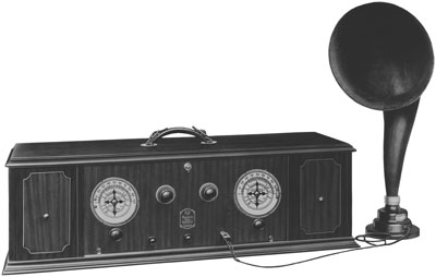
The first commercial superheterodyne, the AR-812, shown in Figures 1 and 2 (see print edition,) was manufactured in early 1924. This radio uses 6 Type UV199 tubes, each drawing only 60 milliamperes of filament current, making dry-cell operation feasible. The radio’s performance is enhanced by the use of reflex circuitry. The RF amplifier is reflexed to function also as an IF amplifier. A single UV199 triode serves as both local oscillator and mixer. Like many early superhets, the AR-812 used a very low IF — in this case 45 kHz. It has only 4 controls — 2 tuning dials and 2 filament rheostats — and a built-in loop antenna. The loop, made for portability, was also advantageous for city dwellers where long wire antennas were difficult to string.
Figure 1. The impressive Universal Trans-Oceanic. Each of the six units is housed in fully shielded cabinets. There are enough controls to satisfy any "knob-twistFigure 1. The AR-812, manufactured in 1924, was the first commercial superhet. The handle on this set qualifies it as a “portable.” (This photo is an RCA publicity photos and is from your Editor’s collection.)
The AR-812 was advertised as a portable set and had a handle on top of a husky wood cabinet (3 feet long!) and built-in battery compartments. Yet, at about 40 pounds, plus the weight of 6 large, dry-cell, A batteries, 4 B batteries, a C battery, and a separate horn-speaker, it required a strong person to lug it around. In addition, it was (still is) a nightmare to repair since all components, except the tubes, tuning capacitors, and coils, were encapsulated in a metal tub filled with sealing wax — the dreaded catacomb. Despite its faults, the AR-812 was an instant success. Thousands were sold without batteries at a hefty $269.
Radio enthusiasts (experimenters, amateurs, serious listeners) did not balk at numerous controls, big tube counts, or heavy battery consumption required by most superhets. Article after article appeared in radio magazines and even ordinary newspapers presenting the various types of superhet circuits being “invented.”
I had never planned to collect antique superheterodynes. They seemed few and far between and were the Rolls Royce of reception. I finally did find an AR-812 six or seven years ago at a hamfest. Fortunately, the catacomb was intact, and the required repairs were mostly mechanical in nature. Since then, I’ve acquired several early superhets using a variety of circuits and features.
For the AR-812, I built an AC power supply to fit in one of the battery compartments and obtained a half dozen UV199s. Combined with a modern dynamic speaker (1940s vintage), the radio worked quite well in the lower part of the broadcast band (500-1200 Kc).
A Radio Man’s Superhet
Most sets developed in the early days of the superhet (1924-1926) were simple modifications of Armstrong’s original ideas. Others were attempts at more radical departures and bore unique names; e.g., Ultradyne, Tropadyne. So long as the other superhets on the market were home-brewed or kits made one at a time, RCA let them alone. They posed no real competition and provided free advertisement.
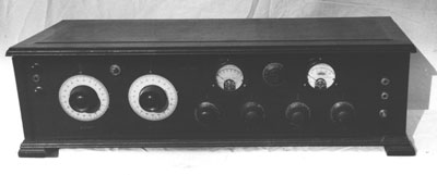
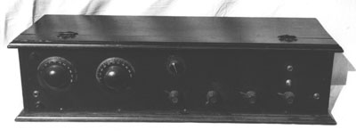
Figure 3. The panel view of a battery-operated superhet, ca. 1925, which was probably built from a kit.
Figure 3 shows the front of an enthusiast’s concept of a superheterodyne. This set was probably built about 1925 and is typical of the 8-tube home brew of the day. The tube lineup is the following: local oscillator, 1st detector, 3 intermediate frequency (IF) amplifier stages, 2nd detector, and 2 audio stages. There are 7 controls: 2 tuning dials, 4 filament rheostats, and a potentiometer that sets the grid bias of the IF stages to control overall gain or to suppress oscillations in the IF amplifiers (by reducing gain). A light bulb mounted between the tuning dials provides illumination for the tuning scales.
Although no manufacturer’s name is given, the radio was probably a kit, since engraved panel markings identify the function of each control. The meters indicate the filament battery voltage (when to recharge the storage battery) and the B battery voltage (when to buy new ones). A panel jack is provided for plugging in a loop antenna. The radio resembles one in a 1925 Popular Mechanix article entitled: “How to Build the Popular Mechanix Superheterodyne Eight.”
Figure 4 (see print edition) is a rear view of the works. The tuning capacitors are Remler clamshell types that provide linear tuning and vernier control via internal gearing. The IF transformers are also Remler. The tubes are Type 201-A which were considered superior to Type UV199. The 8 tubes draw a total of 2 amperes of filament current making an automobile-type storage battery a necessity. After a good cleaning and the usual troubleshooting and repair, the set works well over the entire broadcast band.
LaCault LR-4
The French inventor R.E. LaCault replaced the first detector with a circuit he called a modulator. He claimed that the modulator detected the incoming signal and then used the result to modulate the local oscillator’s amplitude, which was then amplified in the IF amplifier as in an ordinary superhet. He called his radios “Ultradynes” and sold them in America via various companies, the best known being Phenix of Philadelphia. It was claimed that Ultradynes outperformed ordinary superhets in sensitivity and ease of tuning.
I bought a large radio, sight unseen, based on a brief phone description: “large size, 9 tube sockets, many transformers.” When it arrived, I studied its circuitry — it was obviously a superhet of considerable complexity and included a tuned radio frequency amplifier as a front end. The oscillator coil as well as the IF transformers were by Phenix Radio Corporation, a fact that sent me scurrying to my copy of McMahon’s Radio Collector’s Guide. Between 1924-1926, the Phenix Company sold 5- and 8-tube LaCault Ultradynes and kits. Under R.E. LaCault, there was a single entry, a 9-tube Ultradyne kit — the LR-4.
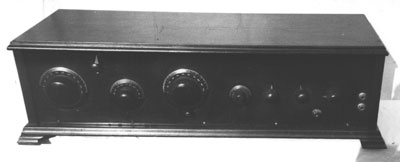
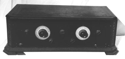
Figure 5. The front panel view of the Ultradyne LR-4 receiver.
My LR-4 was in amazingly good condition; all transformers tested good and all wiring was intact. One audio transformer was missing, and I added it to complete the audio section. The RF amplifier and modulator coils were obviously hand-wound on cardboard tubes. The tight, beautifully finished, hardwood cabinet had apparently preserved the interior contents over the decades. Figure 5 shows the front.
The layout is typical superhet. The knob between the tuning knobs is the potentiometer for setting IF grid bias. The small knob above is a small variable antenna coupling capacitor to prevent overloading the front end. Vernier tuning of the local oscillator is via spur gears. Figure 6 (see print edition) shows the rear view. The mechanically-coupled dual tuning capacitors used to tune the front end were a forerunner of the ganged capacitors still to come.
Did the Ultradyne live up to its billing? Over a series of evening listening sessions I was able to receive AM stations all across the band, including several weak stations I had not received before using other antique radios. In addition, the tuning was remarkably smooth and devoid of the heterodyne whistles one usually gets with antique superhets.
Why did the Utradyne not become more popular? The answer probably lies in the fear of patent litigation since there is no doubt an IF frequency is generated by the modulator which is amplified, as in an Armstrong superhet. Of course, with the advent in the late 1920s of the multigrid tubes where heterodyning occurred inside the tube itself, the question became moot.
The Tropadyne
The Tropadyne was the brainchild of Clyde Fisk, a well-known innovator, and required only 6 tubes — a converter, 3 IF stages, a second detector, and a single audio stage. He combined the local oscillator and first detector in a simple reflex arrangement similar to Armstrong’s original set. My daughter bought the radio at an antique flea market at a modest price, after it had lain for decades in someone’s garret or basement. It was extremely grimy and required a lot of cleaning before repairs could be started.
The IF transformers, which Fisk called “tropaformers,” were bulky affairs that included a compression-type variable capacitor for tuning the secondary. All windings of the four tropaformers tested open and required melting out the sealing wax that held the coils in place. (Apparently the bare copper coil leads had reacted with the paraffin to render the copper brittle.)
After cleaning the soldering lugs and resoldering new connection leads, I repacked the cases with modern plastic stuffing. (This took much longer than it takes to tell.) After reassembling the radio I debugged the remaining circuitry using the usual techniques. I aligned the IF amplifiers by tuning to a strong local station and tuning each tropaformer for the loudest signal, a technique of the 1920s when builders were unlikely to have alignment equipment. The set worked well using either an external loop antenna or a long-wire antenna. The good results I attribute to the IF stages being individually tuned to achieve perfect alignment.
Figure 7. The panel view of the restored Tropadyne receiver.
Figure 7 shows the front of the restored radio. The tuning dials are National “Velvet” verniers. The row of 4 small arrow knobs control the various filaments. The knob at the center-top is the usual potentiometer control for IF bias setting. There is the usual push-type, on-off switch, 2 speaker jacks, terminals for antenna and ground, and a jack for a loop antenna. There are no panel markings, and it is probable that this is a kit or shop radio. Figure 8 (see print edition) shows the well-built insides. A large knob for IF tuning sits atop each tropaformer.
Caution: Visitors seeing these big knobs have the irresistible urge to twist them, thereby detuning the IF amplifier!
Late 1920s Superhet
E.H. Scott is famous for his triode superhets of the last half of the 1920s. They are bulky affairs and much sought after by collectors. I have never seen a Scott battery superhet, and there is little chance of ever obtaining one. The next best thing is superhets by John Victoreen, which seem to be fair copies of the Scotts. I bid for a Victoreen advertised in A.R.C., and after one hike in price, I got it.
Figure 9. The panel view of the Victoreen superheterodyne receiver.
This 7-tube radio had obviously been built from a kit (McMahon’s Radio Collector’s Guide lists a superhet kit by Victoreen in 1928) and modified over the years. Fortunately, the original blueprint schematic came with the radio and enabled me to restore the original circuit.
Figure 9 shows the front panel which departs from the usual early superhet layout. However, there are the usual 2 tuning dials, 4 filament rheostats, the grid-bias potentiometer, a single output jack and a rotary on-off switch. There are no panel markings.
Figure 10 (see print edition) shows the interior. The IF transformers and coils are labeled “‘Victoreen Radio Co.,” the tuning capacitors and knobs are Remler clam-shell types, the audio transformers are by Acme. The cabinet is of the “coffin” type. The restored radio plays well on all local AM stations and is a fine piece of furniture in itself.
NOTE: All of the above described radios use 201-A tubes. All are 2 1/2 to 3 feet in length. and are housed in solid hardwood cabinets.
1928 is a date which must signal the demise of the home-brewed superhet, for in that year, RCA unveiled the Radiola 60. The Model 60 was AC-powered and had 1-dial tuning which anyone could operate. It had a metal chassis, AC-type tubes, and ganged capacitors. The Radiola 60 at $175 introduced the low-cost, modern superhet to the public.
How good was an early battery superhet? I’ve been playing my AR-812 for two or three hours daily for over five years on the same set of tubes (already used when bought), and it’s still perking. The trick, of course, is to run the filaments at a reduced voltage.
Superhet Documentation
For those truly interested in the historic or the technical aspects of the superhet there is plenty of literature available.
Charles Leutz, founder of the Experimenters Information Service in 1921, published a slight volume called Superheterodyne Receivers. In it he describes the heterodyne principle and presents plans for building receivers of his own design. In advertisements for his plans and kits, he shows that you could build your own superhet for 20 percent of the cost of a commercial one.
The book has been reproduced; unfortunately, the blueprint schematics have been photo-reduced to such a small size that they are illegible. In Volume 2 of Radio Manufacturers of the 1920’s, Alan Douglas presents a brief biography of Leutz, as well as excellent pictures of Leutz receivers. Though home-brewed, these radios are much sought after by serious collectors.
The Legacy of Edwin Howard Armstrong, published by the Radio Club of America, is a compendium of articles on Armstrong, who was involved in the patent wars of the 1920s. One article is titled “More Than You Ever Wanted to Know About the Superheterodyne Receiver,” and it lives up to its promise.
Ed Romney’s book Fixing up Nice Old Radios contains much technical information on early superhets, including circuit diagrams and descriptions of the first RCA superhets. It is invaluable should you come upon an early Radiola superhet.
The Super-Heterodyne Book, published by Radio News in 1926, is a resume of the entire superheterodyne art in the mid-1920s. Every type of superheterodyne circuit is described and enough detailed technical and physical data (circuits, drawings, dimensions, construction hints) is included for you to build more than a dozen superhets of your own.
For the less technical there is Lawrence Lessing’s book Man of High Fidelity, a biography of Armstrong. There is also Empire of the Air by Tom Lewis, recounting the interacting lives of Armstrong, inventor of the regenerative circuit, the superheterodyne, and frequency modulation; Dr. Lee de Forest, inventor of the triode vacuum tube, and David Sarnoff, president of RCA. The book vividly records the end of the era of the solitary inventor (Armstrong, de Forest) and the triumph of the corporation (Sarnoff).
During the 1920s, a controversy raged as to who invented the superhet. We Americans championed Armstrong — others gave priority to various Europeans. After almost a decade of legal battle, the courts in 1928 awarded the patents to Lucien Levy, a French inventor. Knowledgeable radio engineers — American and European alike — give credit to Armstrong.
References:
Douglas, Alan. Radio Manufacturers of the 1920’s. Vestal, N.Y.: Vestal Press, Ltd., 1989.
Lessing, Lawrence. Man of High Fidelity: Edwin Howard Armstrong. Philadelphia, Pa.: J.B. Lippincott Company, 1956. Bantam Paperback Edition, 1969.
Leutz, Charles. Superheterodyne Receivers. Milwaukee, Wis.: Experimenters Information Services, Inc., 1924. Reprint distributed by Lindsay Publications, Inc., Bradley, Ill.
Lewis, Thomas S.W. Empire of the Air, The Men Who Made Radio. New York: Harper Collins, 1991.
McMahon, Morgan. Radio Collector’s Guide. Revised Edition. Palos Verde Peninsula, Cal.: Vintage Radio, 1981.
Radio News. The Superheterodyne Book. New York, N.Y.: Experimenters Publishing Co., 1926.
Romney, Edward H. Fixing up Nice Old Radios. Drayton, S.C.: Ed Romney, 1990.
The Radio Club of America. The Legacies of Edwin Howard Armstrong. Radio Club of America, Inc., 1990.
(William Corkutt, 26 Hillside Ave., Monsey, NY 10952)
(Bill Corkutt has been interested in old radios since he bought a junker 3-dialer at a hamfest in 1993. His interest in radio dates back to the early 1950s when he served as an army radio operator during the Korean War. He is a retired electrical engineer and operates amateur radio station WZ2I.)
| [Free Sample] [Books, etc., For Sale] [Subscribe to A.R.C./Renew] [Classified Ads] [Auction Prices] [Event Calendar] [Links] [Home] [Issue Archives] [Book Reviews] [Subscription Information] [A.R.C. FAQ] URL = http://www.antiqueradio.com/corkutt_superhet.html Copyright © 1996-2000 by John V. Terrey - For personal use only. Last revised: July 28, 2000. For Customer Assistance please contact ARC@antiqueradio.com or call (978) 371-0512 Pages designed/maintained by Wayward Fluffy Publications
Antique Radio Classified |